Are you wondering as I was why we decided to develop a Class D amplifier instead of a Class A/B amp like many conventional products on the market use? Whats the difference between the classes anyway? I put on my reporter's hat and headed out to get the scoop. Turns out it's all a matter of efficiency.
First Things First: The Classes
It's impossible to understand what the choice before us is without understanding the different classes of amplifiers. We turn to our guru, Alan Lofft, who explains in an article elsewhere on this site entitled Ten Things You Always Wanted to Know About Amplifiers :
What Are the Different Classes of Amplifiers?
Class A designs have current constantly flowing through the output transistors even if there is no incoming audio signal, so the output transistors are always on. This type of amplifier has the lowest distortion of any but its extremely wasteful and inefficient, dissipating 80% of its power in heat with an efficiency of only 20%.
Class B amplifiers use output transistors that switch on and off, with one device amplifying the positive portion of the waveform, the other device the negative part. If there is no incoming audio signal, then no current flows through the output transistors. Consequently, Class B amplifiers are much more efficient (about 50% to 70%) than Class A designs, however there may be non-linear distortions that occur when one set of transistors switch off and the other set switches on.
Class A/B amplifiers combine the virtues of Class A and Class B designs by having one output device stay on a bit longer, while the other device takes over amplifying the other half of the audio waveform. In other words, there is a small current on at all times in the crossover portion of each output device, which eliminates the potential switching distortion of a pure Class B design. Efficiency of a Class A/B amp is still about 50%.
Class D amplifiers, although there are a number of different design variations, are essentially switching amplifiers or Pulse Width Modulator (PWM) designs. The incoming analog audio signal is used to modulate a very high frequency PWM carrier that works the output stage either fully on or off. This ultra-high frequency carrier must be removed from the audio output with a reconstruction filter so that no ultra-high frequency switching components remain to corrupt the audio signals. As previously mentioned, Class D designs are extremely efficient, typically in the range of 85% to 90% or more.
How Do They Work?
In looking at different amplifier designs, we need to consider the modes in which transistors can operate. When a transistor is operated as a switch, its either fully off (cutoff) or fully on (saturation). When the transistor is in either of those states, its very efficient there are almost no losses in the transistor. But if its operated in a Class A/B amplifier, in the forward active mode, the transistor is always conducting current, even when there is no audio signal. For this most common of amplifier types, the output transistors are essentially always being used, and therefore giving up energy to heat. The more current that flows and the more power that is delivered to the amplifier, the more heat that gets generated.
In a Class D amplifier, the transistors are never used in the active mode like a Class A/B amp. Theyre used in a switching mode where they are always fully off or fully on. This means you can theoretically get nearly 100% efficiency, because the losses are very small.
The problem is how do you switch a transistor or a couple of transistors on and off to create a sine wave? Simply switching them on and off gives you a square wave. But if you look at a sine wave, it goes gradually from zero to positive, then back to zero, and then gradually becomes more and more negative, and then back to zero again. So we need to get the transistors to create a sine wave instead of a square wave. How do we do that? We turn them on and off at a constant rate, between 300,000 and 400,000 times per SECOND.
Next, we have to somehow make those transistors that are switching on and off at extremely high speeds recreate a sine wave or a music signal. To do that we use a technique called Pulse Width Modulation or PWM. All that does is look at the input signal the sine wave, for instance and depending on how positive or how negative the signal happens to be, we change how long the transistors are on and off. If there is no signal coming to the amplifier the wave is steady and regular, like a clock. When we send a signal through, though, what happens is the amount of time the positive or negative transistor is on changes with how positive or negative the input signal is.

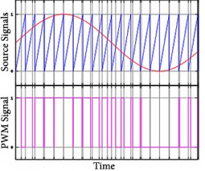
Here is an image showing how pulse width modulation reproduces sound. Original image is borrowed from http://en.wikipedia.org/wiki/Pulse-width_modulation and slightly enhanced.
Let's look at the image to the right. In the top part you can see a sine wave in red. In the lower part of the image, the purple series of rectangular sections, the little rectangles are changing in a manner that perfectly mimics the sine wave. We then use this PWM modulated version of the audio signal as the control signal that varies the timing of the output transistors turning on and off.
So we now have a signal at the output of the amplifier that contains the information about the sine wave that went into the amplifier. Next, we apply a filter to get rid of all that really high frequency stuff that happens beyond the limits of human hearing (that fast 300-400,000 times switching signal).
Even though the output stage is not directly tracking the input signal, those transistors are always operated either fully off or fully on. Because of this theyre always operating in their highest efficiency area, unlike a traditional amplifier.
In effect, were just operating the devices that produce the power in an area where they are far more efficient, and hence the whole amplifier can be more efficient. Its generating less heat and it wastes less wall power. At its most basic, we can illustrate efficiency by taking the example of drawing 100 watts from a wall socket. In a Class A/B amplifier we can get about 50 watts from the amplifier to deliver to the speaker. As you know from your high school physics class, the other 50 watts has to go somewhere, so it becomes heat.
With a Class D amplifier, you draw 100 watts out of the wall and you get 90 delivered to speakers. The importance of this goes far beyond the obvious savings of electricity: it adds greatly to the performance of your system. We all seek a dynamic performance without distortion and the way to achieve it is to have enough power in your amplifier to reproduce those dynamic peaks, which require large amounts of power for short periods of time, without limiting or clipping. An efficient amplifier with a large power supply can do exactly this, and that was the design goal of our Axiom amplifiers.
Now, since most of us have to pay for our electricity, and since most of us don't want to go to the expense of adding a 20 amp circuit to our house to get more power to our home theater speakers, a more efficient amplifier means you can maximize the power to your home theater system by using as much of the power coming from your wall socket as possible to move the drivers on your loudspeakers.
Hopefully this long explanation helps you understand the different amplifier designs and why Axiom has chosen a Class D design for its new home amplifier lineup.