The store will not work correctly in the case when cookies are disabled.
This website requires cookies to provide all of its features. For more information on what data is contained in the cookies, please see our Privacy Policy page. To accept cookies from this site, please click the Allow button below.
We use cookies to make your experience better.Learn more.
Building at Sample Woofer - the Research at AxiomAudio
Building a Sample Woofer
Building sample drive units as they have been designed by Andrew or Ian is an integral part of our testing process. Our in-house machine shop allows us to sample the various metal parts required quite easily and then it is time for assembly of the sample driver. Below is a look at some of the steps involved.
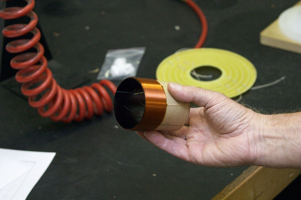
Alan Lofft holds the large two-inch woofer voice coil on its assembly, the starting piece for building a sample woofer.
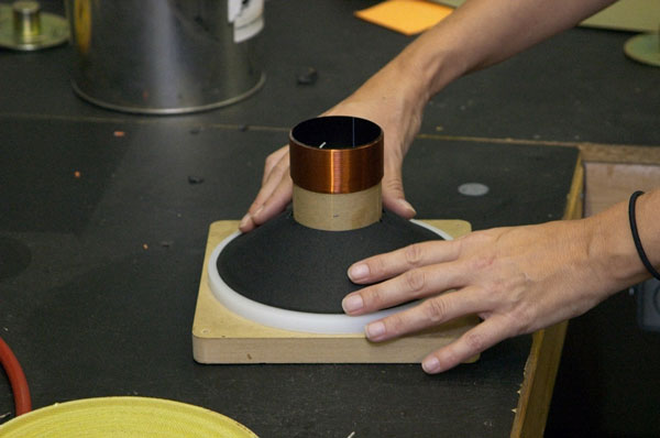
Debbie Swinton prepares a mounting jig for the voice coil, to which the aluminum cone is attached later in the process.
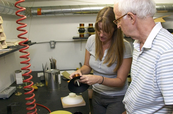
Debbie removes the installed voice coil assembly from the mounting jig.
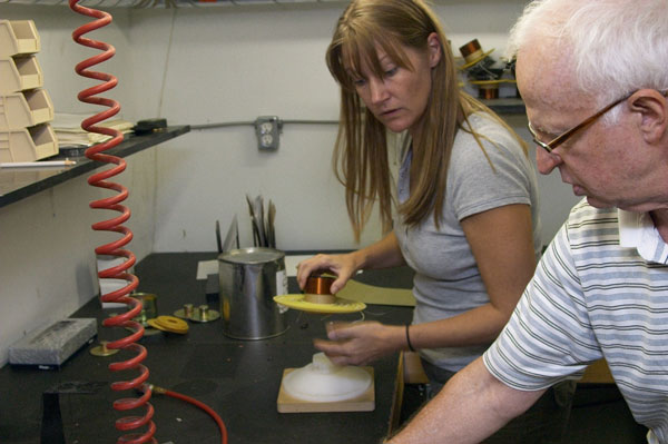
Here Debbie has attached the voice coil to the flexible spider.
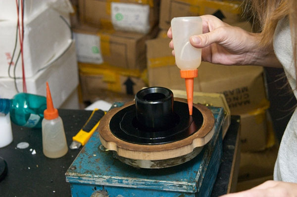
A layer of glue is applied to the base of the magnet assembly.
The ferrite magnet is glued to the magnet assembly. Later on, the ferrite core will be magnetized in Axiom's magnetizer.
Here she glues a retainer ring to the ferrite magnet. The retainer ring and magnet assembly will be attached to the large aluminum woofer basket.
In this picture, Debbie screws the cast aluminum basket to the speaker magnet assembly.
The completed aluminum basket with its attached woofer magnet structure.
Debbie uses a jig to center the voice coil and spider assembly in the center of the magnet structure, and glues it into place.
A bead of glue is applied to the voice coil spider assembly, ready to receive the aluminum woofer cone.
Finally, Debbie takes the aluminum cone and its composite rubber surround to glue it to the basket and voice-coil assembly.
Debbie shows the completed 12-inch woofer driver, ready for testing.
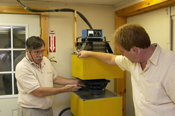
When a test woofer is built at Axiom, the magnet core material is unmagnetized. This machine magnetizes the woofer magnets.